Eurocode 3: Design of steel structures - Part 1-8: Design of joints
Design assumptions
(1) Joints shall be designed on the basis of a realistic assumption of the distribution of internal forces and moments. The following assumptions shall be used to determine the distribution of forces:
(a) the internal forces and moments assumed in the analysis are in equilibrium with the forces and moments applied to the joints,
(b) each element in the joint is capable of resisting the internal forces and moments,
(c) the deformations implied by this distribution do not exceed the deformation capacity of the fasteners or welds and the connected parts,
(d) the assumed distribution of internal forces shall be realistic with regard to relative stiffnesses within the joint,
(e) the deformations assumed in any design model based on elastic-plastic analysis are based on rigid body rotations and/or in-plane deformations which are physically possible,
(f) any model used is in compliance with the evaluation of test results (see EN 1990).
Connections made with bolts, rivets or pins
Bolts, nuts and washers
General
(1) All bolts, nuts and washers should comply with 1.2.4 Reference Standards: Group 4.
(2) The rules in this Standard are valid for the bolt classes given in Table 3.1.
(3) The yield strength $f_{yb}$ and the ultimate tensile strength $f_{ub}$ for bolt classes 4.6, 5.6, 5.8, 6.8, 8.8 and 10.9 are given in Table 3.1. These values should be adopted as characteristic values in design calculations.
Preloaded bolts
(1) Only bolt assemblies of classes 8.8 and 10.9 conforming to the requirements given in 1.2.4 Reference Standards: Group 4 for High Strength Structural Bolting for preloading with controlled tightening in accordance with the requirements in 1.2.7 Reference Standards: Group 7 may be used as preloaded bolts.
Categories of bolted connections
Shear connections
(1) Bolted connections loaded in shear should be designed as one of the following:
Category A: Bearing type
In this category bolts from class 4.6 up to and including class 10.9 should be used. No preloading and special provisions for contact surfaces are required. The design ultimate shear load should not exceed the design shear resistance, obtained from 3.6, nor the design bearing resistance, obtained from 3.6 and 3.7.
Category B: Slip-resistant at serviceability limit state
In this category preloaded bolts in accordance with 3.1.2(1) should be used. Slip should not occur at the serviceability limit state. The design serviceability shear load should not exceed the design slip resistance, obtained from 3.9. The design ultimate shear load should not exceed the design shear resistance, obtained from 3.6, nor the design bearing resistance, obtained from 3.6 and 3.7.
Category C: Slip-resistant at ultimate limit state
In this category preloaded bolts in accordance with 3.1.2(1) should be used. Slip should not occur at the ultimate limit state. The design ultimate shear load should not exceed the design slip resistance, obtained from 3.9, nor the design bearing resistance, obtained from 3.6 and 3.7. In addition for a connection in tension, the design plastic resistance of the net cross-section at bolt holes $N_{net,Rd}$, (see 6.2 of EN 1993-1-1), should be checked, at the ultimate limit state.
The design checks for these connections are summarized in Table 3.2.
Tension connections
(1) Bolted connection loaded in tension should be designed as one of the following:
Category D: non-preloaded
In this category bolts from class 4.6 up to and including class 10.9 should be used. No preloading is required. This category should not be used where the connections are frequently subjected to variations of tensile loading. However, they may be used in connections designed to resist normal wind loads.
Category E: preloaded
In this category preloaded 8.8 and 10.9 bolts with controlled tightening in conformity with 1.2.7 Reference Standards: Group 7 should be used.
The design checks for these connections are summarized in Table 3.2.
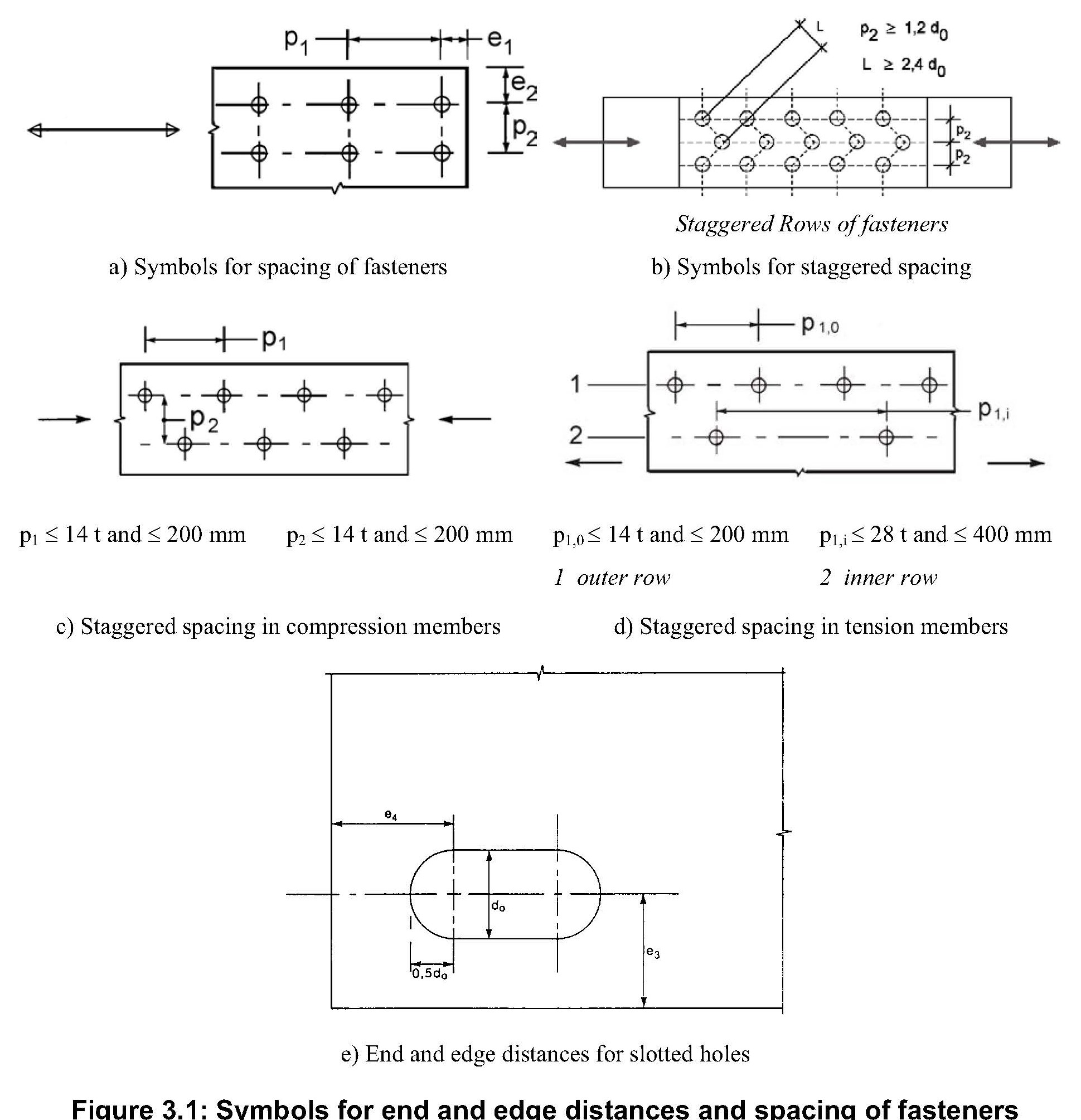
Positioning of holes for bolts and rivets
(1) Minimum and maximum spacing and end and edge distances for bolts and rivets are given in Table 3.3.
(2) Minimum and maximum spacing, end and edge distances for structures subjected to fatigue, see EN 1993-1-9.
Design resistance of individual fasteners
Bolts and rivets
(1) The design resistance for an individual fastener subjected to shear and/or tension is given in Table 3.4.
(2) For preloaded bolts in accordance with 3.1.2(1) the design preload, $F_{p,Cd}$ ,to be used in design calculations should be taken as:
$$F_{p,Cd}=0.7f_{ub}A_{s}/\gamma _{M7}$$ NOTE: Where the preload is not used in design calculations see not to Table 3.2.
(3) The design resistances for tension and for shear through the threaded portion of a bolt given in Table 3.4 should only be used for bolts manufactured in conformity with 1.2.4 Reference Standard: Group 4.
For bolts with cut threads, such as anchor bolts or tie rods fabricated from round steel bars where the threads comply with EN 1090, the relevant values from Table 3.4 should be used.
For bolts with cut threads where the threads do not comply with EN 1090 the relevant values from Table 3.4 should be multiplied by a factor of 0.85.
(4) The design shear resistance $F_{v,Rd}$ given in Table 3.4 should only be used where the bolts are used in holes with nominal clearances not exceeding those for normal holes as specified in 1.2.7 Reference Standards: Group 7.
(5) M12 and M14 bolts may also be used in 2 mm clearance holes provided that the design resistance of the bolt group based on bearing is less than or equal to the design resistance of the bolt group based on bolt shear. In addition for class 4.8, 5.8, 6.8, 8.8 and 10.9 bolts the design shear resistance $F_{v,Rd}$ should be taken as 0.85 times the value given in Table 3.4.
(6) Fit bolts should be designed using the method for bolts in normal holes.
(7) The thread of a fit bolt should not be included in the shear plane.
(8) The length of the threaded portion of a fit bolt included in the bearing length should not exceed 1/3 of the thickness of the plate, see Figure 3.2.
(9) The hole tolerance used for fit bolts should be in accordance with 1.2.7 Reference Standards: Group 7.
(10) In single lap joints with only one bolt row, see Figure 3.3, the bolts should be provided with washers under both the head and the nut. The design bearing resistance $F_{b,Rd}$ for each bolt should be limited to:
$$F_{b,Rd}=1.5f_{u}dt/\gamma _{M2}$$ NOTE: Single rivets should not be used in single lap joints.
(11) In the case of class 8.8 or 10.9 bolts, hardened washers should be used for single lap joints with only one bolt or one row of bolts.
(12) Where bolts or rivets transmitting load in shear and bearing pass through packing of total thickness $t_{p}$ greater than one-third of the nominal diameter $d$, see Figure 3.4, the design shear resistance $F_{v,Rd}$ calculated as specified in Table 3.4, should be multiplying by a reduction factor $\beta _{p}$ given by:
$$\beta _{p}=\frac{9}{8d+3t_{p}}$$ but $\beta _{p} \le 1$
(13) For double shear connections with packing on both sides of the splice, $t_{p}$ should be taken as the thickness of the thicker packing.
(15) For grade S 235 steel the “as driven” value of $f_{ur}$ may be taken as 400 N/mm2.

Group of fasteners
(1) The design resistance of a group of fasteners may be taken as the sum of the design bearing resistances $F_{b,Rd}$ of the individual fasteners provided that the design shear resistance $F_{v,Rd}$ of each individual fastener is greater than or equal to the design bearing resistance $F_{b,Rd}$ . Otherwise the design resistance of a group of fasteners should be taken as the number of fasteners multiplied by the smallest design resistance of any of the individual fasteners.
Long joints
(1) Where the distance $L_{j}$ between the centres of the end fasteners in a joint, measured in the direction of force transfer (see Figure 3.7), is more than $15d$, the design shear resistance $F_{v,Rd}$ of all the fasteners calculated according to Table 3.4 should be reduced by multiplying it by a reduction factor $\beta _{Lf}$, given by:
$$\beta _{Lf}=1-\frac{L_{j}-15d}{200d}$$ $\beta _{Lf} \le 1.0$ but $\beta _{Lf} \ge 0.75$
(2) The provision in 3.8(1) does not apply where there is a uniform distribution of force transfer over the length of the joint, e.g. the transfer of shear force between the web and the flange of a section.
Slip-resistant connections using 8.8 or 10.9 bolts
Design Slip resistance
(1) The design slip resistance of a preloaded class 8.8 or 10.9 bolt should be taken as:
$$F_{s,Rd}=\frac{k_{s}n\mu}{\gamma _{M3}}F_{p,C}$$ $$F_{s,Rd,ser}=\frac{k_{s}n\mu}{\gamma _{M3,ser}}F_{p,C}$$ where:
$k_{s}$ is given in Table 3.6
$n$ is the number of the friction planes
$\mu$ is the slip factor obtained either by specific tests for the friction surface in accordance with 1.2.7 Reference Standards: Group 7 or when relevant as given in Table 3.7.
(2) For class 8.8 and 10.9 bolts conforming with 1.2.4 Reference Standards: Group 4, with controlled tightening in conformity with 1.2.7 Reference Standards: Group 7, the preloading force $F_{p,C}$ to be used in equation (3.6) should be taken as:
$$F_{p,C}=0.7f_{ub}A_{s}$$ 

Combined tension and shear
(1) If a slip-resistant connection is subjected to an applied tensile force, $F_{t,Ed}$ or $F_{t,Ed}$,ser, in addition to the shear force, $F_{v,Ed}$ or $F_{v,Ed,ser}$, tending to produce slip, the design slip resistance per bolt should be taken as follows:
for a category B connection: $$F_{v,Ed,ser}=\frac{k_{s}n \mu (F_{p,C}-0.8F_{t,Ed,ser})}{\gamma _{M3,ser}}$$ for a category C connection:
$$F_{v,Ed}=\frac{k_{s}n \mu (F_{p,C}-0.8F_{t,Ed})}{\gamma _{M3}}$$ (2) If, in a moment connection, a contact force on the compression side counterbalances the applied tensile force, no reduction in slip resistance is required.
Deductions for fastener holes
General
(1) Deduction for holes in the member design should be made according to EN 1993-1-1.
Design for block tearing
(1) Block tearing consists of failure in shear at the row of bolts along the shear face of the hole group accompanied by tensile rupture along the line of bolt holes on the tension face of the bolt group.
(2) For a symmetric bolt group subject to concentric loading the design block tearing resistance, $V_{eff,1,Rd}$ is given by:
$$V_{eff,1,Rd}=f_{u}A_{nt}/\gamma _{M2}+(1/\sqrt{3})f_{y}A_{nv}/\gamma _{M0}$$ $A_{nt}$ is net area subjected to tension;
$A_{nv}$ is net area subjected to shear.
(3) For a bolt group subject to eccentric loading the design block shear tearing resistance $V_{eff,2,Rd}$ is given by:
$$V_{eff,2,Rd}=0.5f_{u}A_{nt}/\gamma _{M2}+(1/\sqrt{3})f_{y}A_{nv}/\gamma _{M0}$$ 
Prying forces
(1) Where fasteners are required to carry an applied tensile force, they should be designed to resist the additional force due to prying action, where this can occur.
NOTE: The rules given in 6.2.4 implicitly account for prying forces.
Distribution of forces between fasteners at the ultimate limit state
(1) When a moment is applied to a joint, the distribution of internal forces may be either linear (i.e. proportional to the distance from the centre of rotation) or plastic, (i.e. any distribution that is in equilibrium is acceptable provided that the resistances of the components are not exceeded and the ductility of the components is sufficient).
(2) The elastic linear distribution of internal forces should be used for the following:
– when bolts are used creating a category C slip-resistant connection,
– in shear connections where the design shear resistance $F_{v,Rd}$ of a fastener is less than the design bearing resistance $F_{b,Rd}$,
– where connections are subjected to impact, vibration or load reversal (except wind loads).
(3) When a joint is loaded by a concentric shear only, the load may be assumed to be uniformly distributed amongst the fasteners, provided that the size and the class of fasteners is the same.